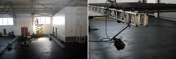
Installation Day #2 for the Pickles Pavilion for the Slow Food Nation event in San Francisco, CA.


SLOW FOOD NATION INSTALL DAY 1
Installation Day #1 for the Pickles Pavilion for the Slow Food Nation event in San Francisco, CA.


SLOW FOOD NATION PARAMETRICS
I finally finished the script for the exhibition space we have designed where we suspend 3024 mason jar lids from a T-bar ceiling. In order to streamline the process, I used the Grasshopper plug-in to parametrically control several aspects of the design. Below, I try to explain each step of the process and how the script works. This script is much more detailed than the previous version, as now all of the steps are embedded into 2 scripts: one grasshopper definition which deals with all of the math behind the project, and one rhinoscript that deals with exporting the data to Microsoft Excel for easy access.
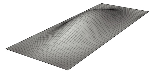
Step 1: The script needs a surface that is larger than the point grid area in order to function properly, so the first step is to generate a sufrace using any of Rhino's surface creation methods. This is the only step that is required prior to launching Grasshopper and running the definition. Click image for more detail.

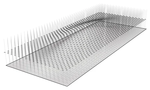
Step 2: The first part of the definition creates a staggered point grid based on a variable offset distance (inches) which is parametrically driven by an integer slider labeled "point spacing". It is important that the point grid is created above the surface (z-axis). Click image for more detail.

Step 3: The next part of the definition duplicates the staggered point grid created in Step 2 and moves them along the z-axis so that the copies are below the given surface. Next, a vertical line is created between the original point grid and the duplicates. Click image for more detail.

Step 4: The definition uses a surface-curve intersection event to create a new point at the location where the vertical lines created in Step 3 intersect the surface. A new line is then created from the new intersection points and the original point grid created in Step 2. Click image for more detail.
Step 5: The script then uses a few components and functions to create a label that defines what panel the vertical line will be attached to, what lid will be attached to the vertical line, and the length of each line. A text tag is placed at the midpoint of each line similar to: "Panel1_Lid1 72.000". The distance is measured in inches and rounds the length of the line to the nearest one thousandth. All text tags must be baked into the scene in order to export the data to excel. (special thanks to Troy Zezula for collaborating on this part of the script). Click image for more detail.

Step 6: Once all of the text tags have been baked into the scene, use the "Load Script" command and locate the rhinoscript called "Export_curvedata_excel.rvb". The use the "Run Script" command and select the loaded rhinoscript from the menu. Follow the on screen directions in the command prompt and select all of the text tags. Excel will automatically open, and a new file will be created with the panel labels and lengths organized for easy access. Within Excel you can convert the length stored from Rhino (rounded to the nearest one thousandth) into a more managable dimension using feet and inches and a specified tolerance. Click image for more detail.
ANIMARIS RHINOCEROS MECHANISM

With a background in science from the University of Delft in Holland, Theo Jansen's kinetic sculptures inspire a sense of wonder at the complexity of nature. For the past 10 years, he has explored the idea of making mechanisms that walk in the wind, ultimately generating a series of "beasts" that rome the beaches living out their own lives. While there are a full series of sculptures, I found the Animaris Rhinoceros sculpture particularly interesting. I decided that I would need to create an interactive digital model of the system to understand the mechanics behind the design. The digital model uses Inverse Kinematics and Bones in 3D Studio Max to create the connections needed for the machine. Essentially, each side of the model is rigged with Inverse Kinematic solvers and then parented to an invisible "Crank" in the middle. By rotating the center crank (named Crank1) around the Y-axis, the system begins to "walk" forwards or backwards depending on the rotation of the crank. Once the initial rig is created, it can be instanced to create the full system as shown in Mr. Jansens actual sculpture.
Download Animaris Rhinoceros.zip (3D Studio Max 9 size: 39k)
Note: This software and its documents are in the public domain and are furnished "as is". The author, Andrew Payne, makes no warranty, expressed or implied, as to the usefulness of the software and documentation for any purpose. This work is licensed under a Creative Commons Attribution-Share Alike 3.0 United States License. http://creativecommons.org/licenses/by-sa/3.0/us/
TENSEGRITY WALL
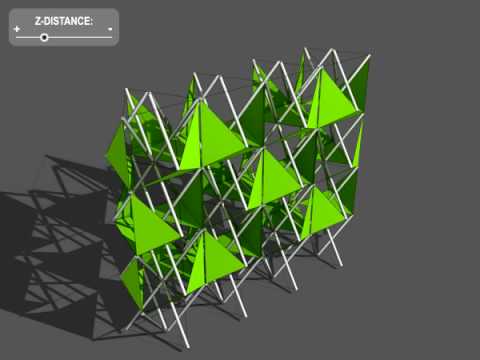
After a long time coming, I finally decided to continue my research on actuated tensegrity systems. I had already created a fully rigged tensegrity module whose compression member's rotation was driven by the distance from the apex of the system to the midpoint. This distance was wired to a slider in the 3D Max file, so the user can easily drive the system by the use of one simple device. However, to complicate matters a little bit, I decided it would be more interesting to rig these modules up into a system, or a wall type structure where all the modules were connected and thus getting more displacement out of the design. Through a little more math and a lot more time, I was able to create a 4x4 wall system that is fully controlled by the same slider that controls the vertical movement of an actuator inserted in the middle of each module (which would ultimately control the distance from the apex to the midpoint). This system could be configured to work with a sensor so that the structure could change shape according to various environmental stimuli.
Download Tensegrity Wall.zip
Note: This software and its documents are in the public domain and are furnished "as is". The author, Andrew Payne, makes no warranty, expressed or implied, as to the usefulness of the software and documentation for any purpose. This work is licensed under a Creative Commons Attribution-Share Alike 3.0 United States License. http://creativecommons.org/licenses/by-sa/3.0/us/
CANTILEVERED BOOKSHELF


This is a remake of a cantilevered bookshelf I made few years ago. The concept is the same as the previous version, however I've simplified the design and eliminated any kind of connection pieces between the counter weight and the steel plate. Essentially, this bookshelf can be made with one precast concrete counter weight, one structural steel channel, and one custom piece of sheet steel slotted down the middle to accommodate and adjustable bookend (not shown) to stop the books from toppling over as they are placed farther down the shelf.