The following are a series of diagrams that help explain the parametric process I used for the FLUX Exhibition which opens in San Francisco on Monday, March 30th. The entire project was completed using the Grasshopper plugin for Rhino and was used to create all of the flattened information - such as the rib outlines, the plexiglass panels, and all corresponding connection details - which was then sent directly to the CNC mill for fabrication.
STEP 1: A series of points, pre-definied in three dimensional space, are referenced into the parametric software. The points can be controlled by a set of sliders that allow translation along any of the orthographic axes, ultimately driving the shape of each interpolated curve that passes through the control points.
STEP 2: A set of planes are created at 10½” O.C. along the full length of the curve network. The distance between each plane, which controls the spacing between each rib, can be updated by changing a numeric slider.
STEP 3: Because some of the interpolated lines in the curve network do not run the full length of the nave, but instead branch off of the two main lines, the topology of the curves would yeild an unloftable surface. However, the software can solve the intersection between a plane and a curve which results in a point. A line can be created between each new intersection point to form the outlines of each rib.
STEP 4: The outside rib curves are offset 4” to create the inside of each rib curve. The ribs are then split into four modules for easier installation.
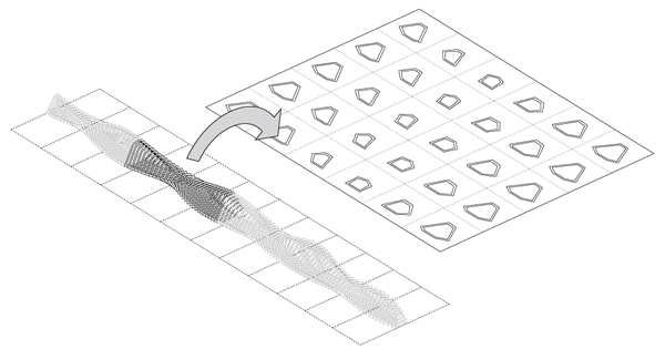
STEP 5: Each rib set is then re-oriented to the XY plane to facilitate the CNC milling process.
STEP 6: Once the rib curves have been flattened, the outlines can be offset and subdivided to create a series of notches in the ribs and the corresponding tabs on each side of the plexiglass panels. The software evaluates the length of each piece of plexiglass and determines the number of subdivisions on each side, so that longer panels have more tabs and thus more support than smaller pieces.
STEP 7: A detail view of a flattened rib and the corresponding pleixglass panels. The perforations that occur in some of the panels are created in Rhinoscript and are coordinated with one of the eight architectural topics represented in the exhibition.
A screenshot of the final definition used to create the entire FLUX exhibition. Click to enlarge.


